
84-87 Civic/CRX Swap Wiring
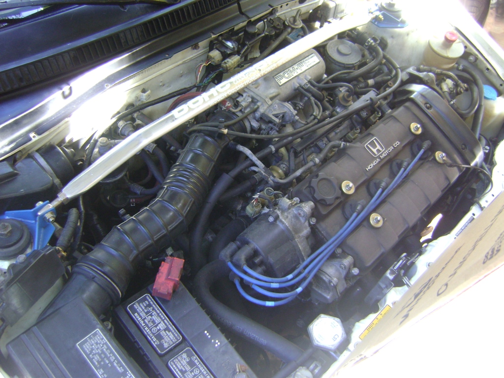
*Read this!* I am posting up this page as-is temporarily as a reference. I still need to upload tons of pictures, and I also need to edit/add lots of content. Since I last updated this back in 2011, I have performed a few more 1G/3G swaps ('86 Si/B16B, carbureted chassis/D16A1, etc.) so I need to add lots of new information relating to those experiences.
This is probably one of my favorite swap recepients. I've done a few 1G/3Gs and kept good notes and finally got a chance to organize them all together. None of the stuff is really new or groundbreaking but I wanted to bring some of my ideas and techniques to the table.
I've done carb to Browntop (86-87 Integra), Si to Browntop and Si to Blacktop (88-89 Integra) swaps. This is mostly going to be wiring info but I'll try to give some insight into the fuel system mods involved in an FI conversion. It's been a while since I did a carb to FI swap so I may have forgotten a few things though. Also this isn't gonna be a step-by-step thing, instead I hope to touch on the basics to give an idea of what's involved.
I organized my notes into 4 sections: Carb to Browntop, Si to Browntop and two versions of Si to Blacktop. I've done the Blacktop swap the "easy way" (quick and easy) and the "hard way" (a little bit cleaner and stock looking). I'm also gonna give a primer on parts needed and techniques that apply to all the swaps.
It is generally recommended on most Honda swaps to re-use the original engine harness that came on your chassis and modify/add wires as needed. On 1G CRX/3G Civics, however, I find that an Integra engine harness of the appropriate year (86-87 Integra for vacuum advance, 88-89 for electronic) greatly cuts down on the amount of wiring you need to do. This holds true for D16A1/ZC swaps and sometimes even B-series engines (with some mods). Most of the wires match up, so it is easier to add wiring to the chassis side of the harness and make the Integra harness plug and play.
For example, an 88-89 Integra engine harness only needs 7 wires added on the chassis side and a few wires switched around on the accessory connector to be plug and play on an 86-87 Si. An 86-87 Integra engine harness is even easier, with only one wire needed to be added on the driver's side connector and a few switched around on the accessory plug. Seven wires may sound like a lot, but consider the engine harness has 33 pinouts in use and extensive shortening/lengthening/adding of wires would be needed to make a stock Si harness work. Make your swap easier and use an Integra engine harness.
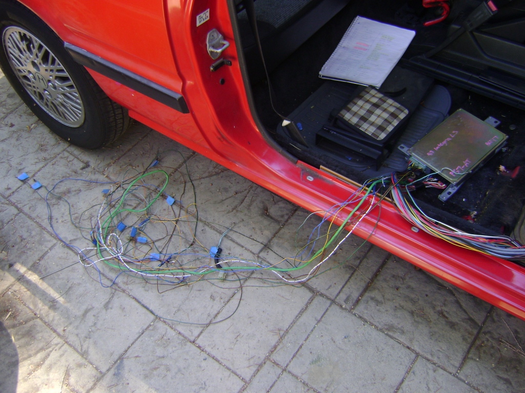
When doing a carb to FI swap or Si to Blacktop swap, it is a good idea to get a complete Integra chassis harness. The rearmost tail light and headlight wiring up front is not needed, only the fuel injection stuff from the ECU plugs under the passenger seat up to the engine harness plugs going into the engine bay, and some of the stuff under the dash (including Main Relay and PA sensor). The pictures below gives you a good idea of how much is needed:
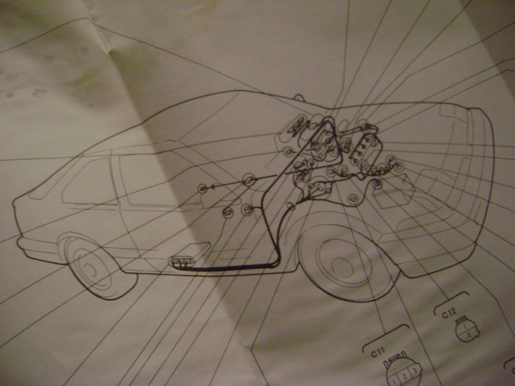
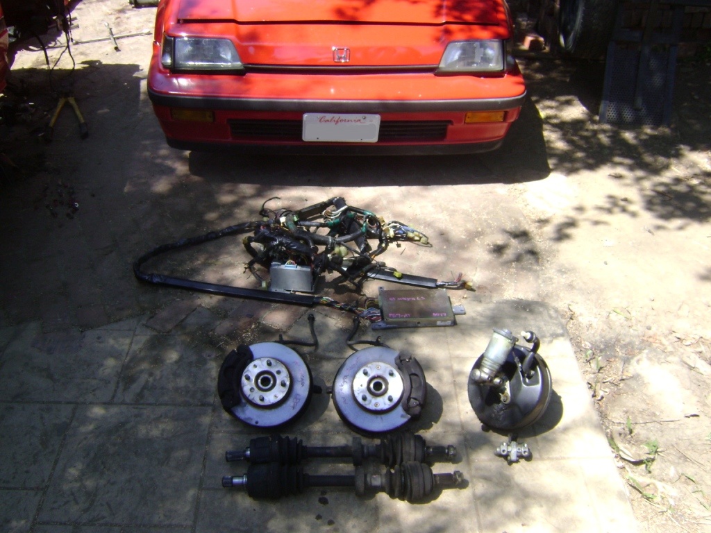
Most of this harness will end up being junk, but it is best to score one complete so you can decide what and how much of it you need to use.
Accessory Plug
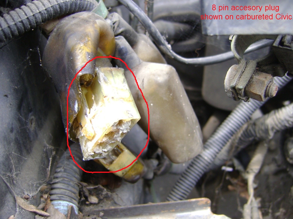
All carb and FI 84-87s have an 8-pin accessory plug connecting to the passenger side engine harness. This is the connector that handles stuff like oil pressure and coolant temp senders, starter signal, reverse lights and fuel injection system ground. On most swaps you will have to swap pins around and occasionally add/remove wires from this plug. Below is a pinout diagram for each harness type:
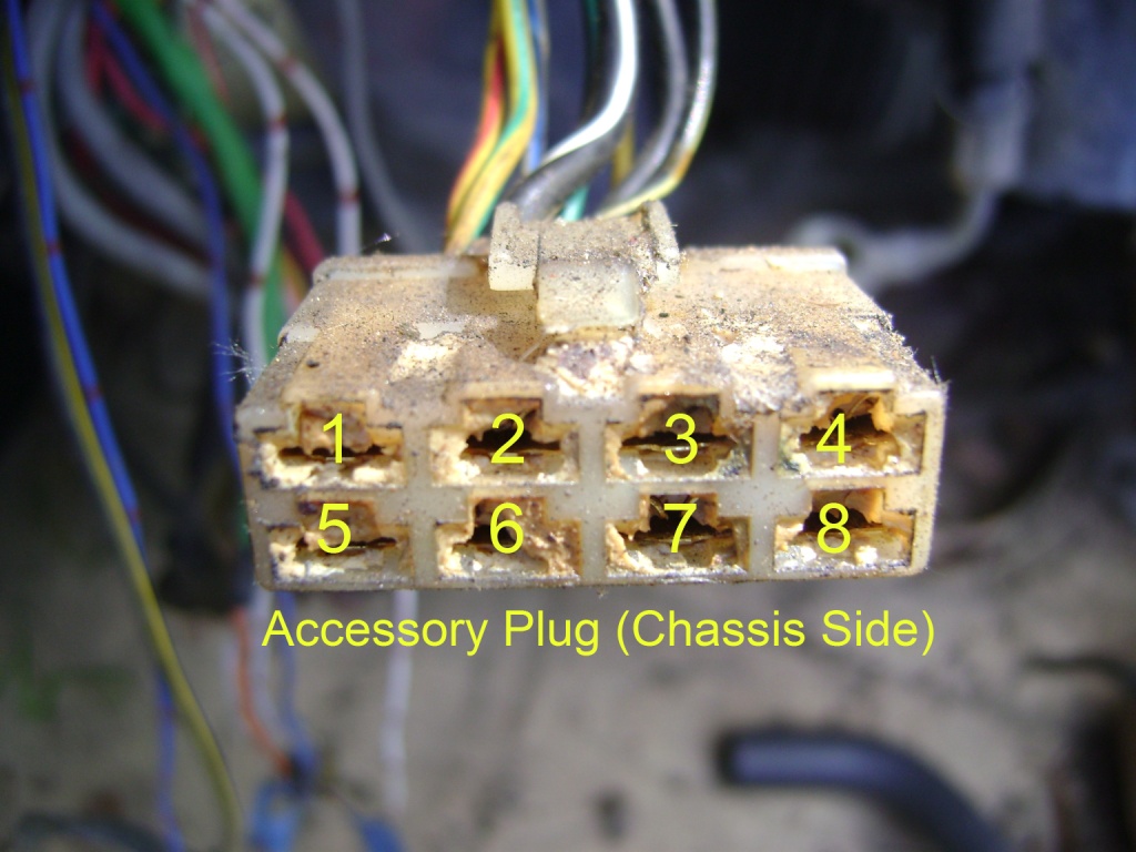
| Carb | Si | Browntop | Blacktop | |
| 1. | YEL/GRN TEMP | YEL/GRN TEMP | GRN/BLK REVERSE | BLK/YEL COIL PWR |
| 2. | BLK/WHT START | BLK/WHT START | BLK/WHT START | BLK/WHT START |
| 3. | WHT/BLU ALT | WHT/BLU ALT | WHT/BLU ALT | WHT/BLU ALT |
| 4. | BLK/YEL PWR | BLK/YEL PWR | BLK/YEL PWR | BLK/YEL PWR |
| 5. | YEL/RED OIL PRES | YEL/RED OIL PRES | YEL REVERSE | BLU TACH SIGNAL |
| 6. | GRN/BLK REVERSE | GRN/BLK REVERSE | YEL/GRN TEMP | YEL/GRN TEMP |
| 7. | YEL REVERSE | YEL REVERSE | YEL/RED OIL PRES | YEL/RED OIL PRES |
| 8. | (NOT NEEDED) | BLK EFI GND | BLK EFI GND | BLK EFI GND |
I compiled this info after swapping a 1987 model D16A1 Integra engine into a carbureted 1985 CRX DX. It has been about 5 years since I did this swap so some of the details are kind of hazy. You should be able to get a good idea of what was needed though.
I pulled out a complete interior/chassis harness out of a 1987 Integra and proceded to isolate only the fuel injection stuff and get rid of the rest. Most of what I removed consisted of HVAC, lighting, stereo and other non-EFI related wiring. Mostly I followed the fuel injection wiring working my way out from the ECU plugs and clipped what I thought wasn't needed, but refered to the Integra FSM when I got stuck. At the end my harness looked more or less like this:
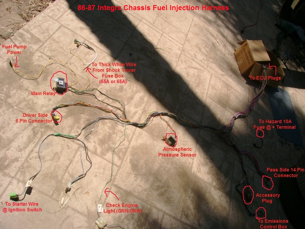
Note the main relay and PA sensor still attatched to the harness. When I went to splice the harness into the CRX I tried to mimic the way those components mouned under the dash in the Integra.
Carbureted Civic's and CRX's have emissions wiring that won't be needed with the new swap. It's up to you if it's worth the trouble to tear into your harness and remove all this wiring or not. On this particular CRX I decided to remove unneeded emissions wiring to clean everything up and make it look more OEM once the swap was complete. However, since I performed this swap so long ago I can't remember what was involved and can't be of much help in this area. Should be pretty self explanitory though.
The original CRX accessory plug wiring (idiot lights, starter signal,etc.) was kept to make things easier.
The picture above pretty much explains the connections needed to splice the Integra harness into the CRX. When seperating the harness, I made sure to note where it tapped into for power and labeled these connections. Once it was installed it looked like this:
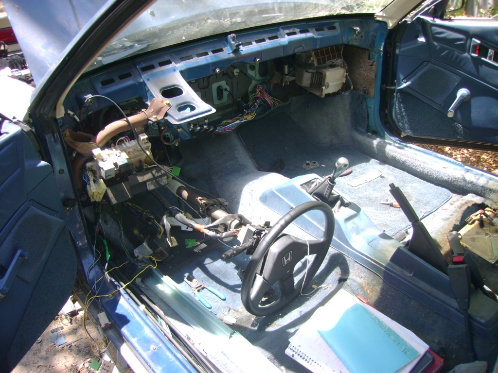
After it was in, all that was needed was to run a power wire to the new electric fuel pump and a single wire for the Check Engine Light.
FUEL SYSTEM
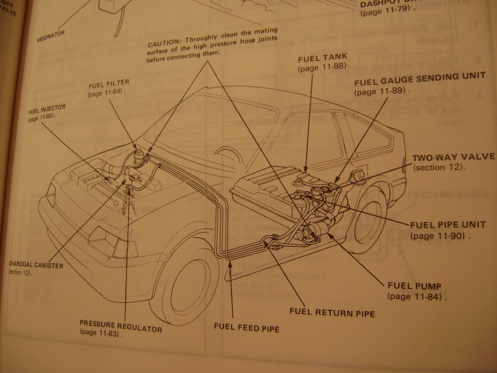
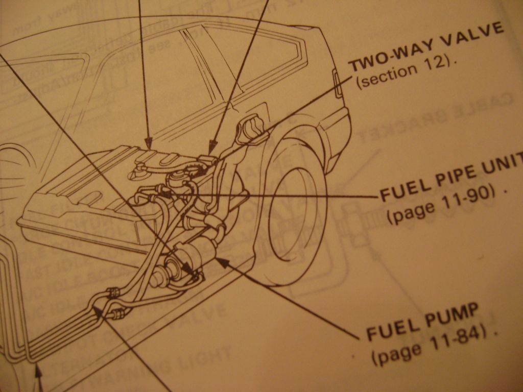
While all the dash components were out, I ran high-pressure Si fuel feed and return lines. I chose to keep the original carbureted vapor line, however it interfered with the Si fuel filter (mounted in the OE Si position). I recommend using all 3 Si lines (feed, return and vapor) and drilling a hole for the new vapor line for the best fit. There are also a couple of fuel filter brackets that should be cut out of a donor car and welded to the DX firewall for the complete OEM look.
The rest of the fuel system consisted of a stock DX tank, Si pickup (fuel pipe unit) and Si pump/bracket assembly. If you can, try and get your hands on a good Si tank. It uses baffles around the pickup to help prevent fuel starvation when going around corners on a low tank.
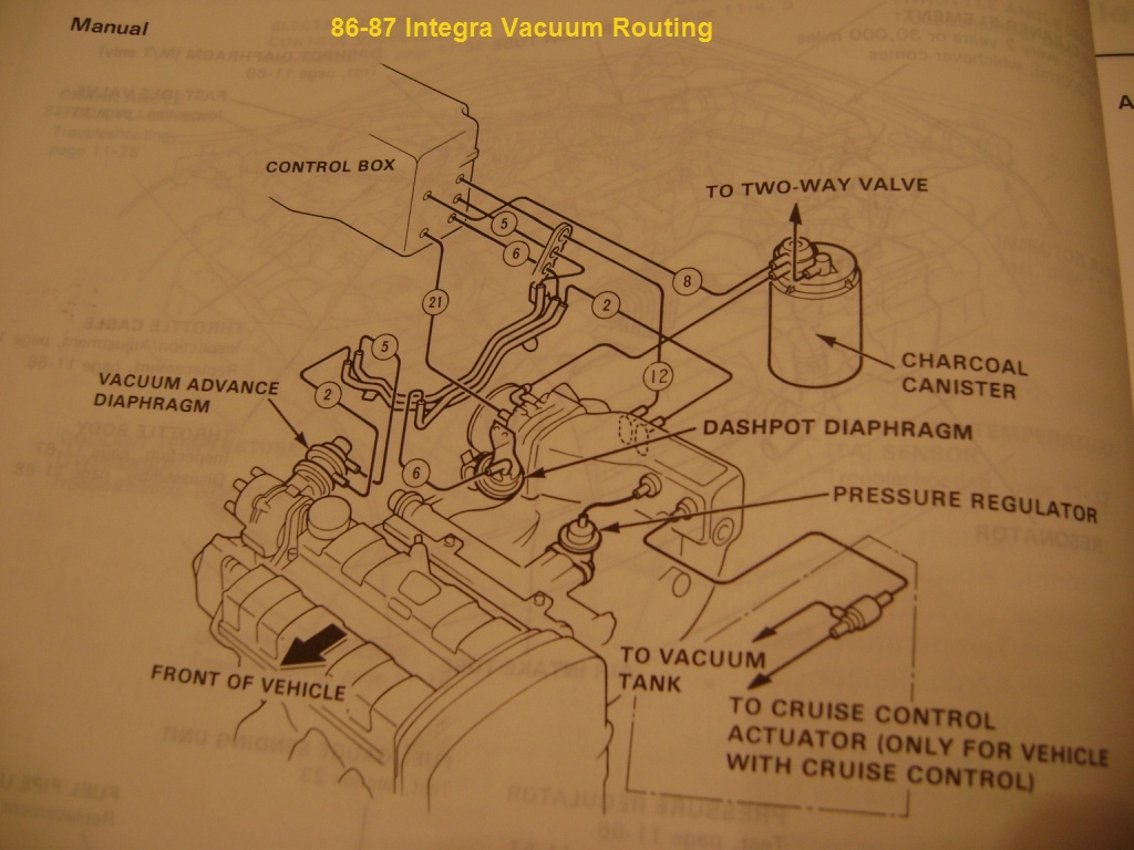
VACUUM ROUTING
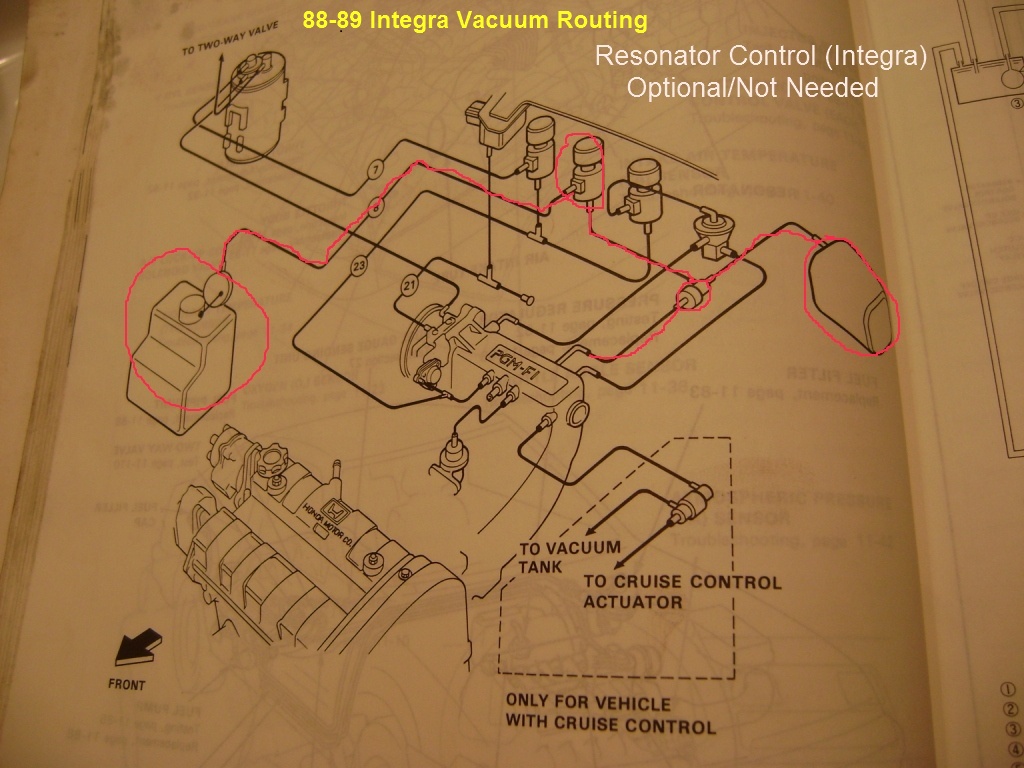
A 1987 5MT Integra emissions control box was used. It plugged right into the new Integra harness and bolted up to the stock CRX firewall. Below is a pic of the hose routing:
MISCELLANEOUS
To avoid having to wire it, the VSS circuit was removed from the Integra harness (ECU pin B18). It's not needed and the Browntop Integra ECU will not throw a trouble code without it.
A 1985 CRX Si instrument cluster was used for its check engine light and 140mph speedo. The GRN/ORN CEL wire was pinned into the cluster plug, however I don't remember which pin it was.
The 8-pin accessory plug had to be repinned. Refer to the pinout diagram in the primer for details.
Final Install:
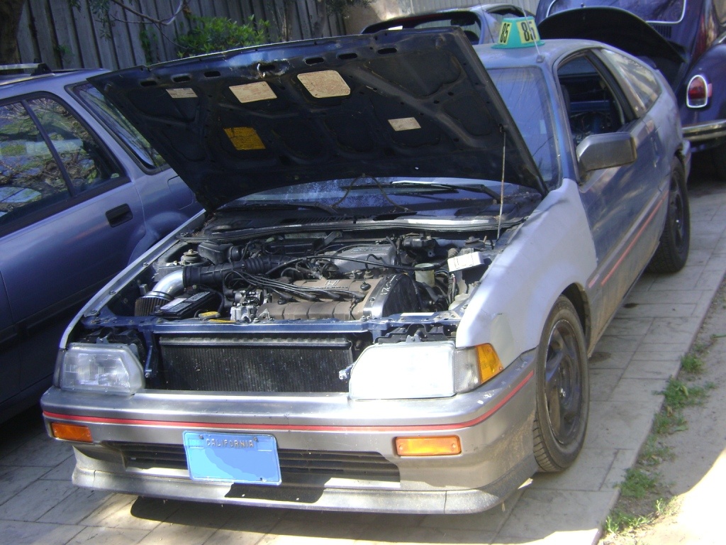
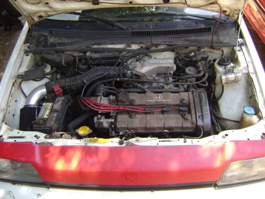
This is the easiest of these 3 swaps. The wiring pretty much consists of plugging in an 86-87 Integra harness, swapping some pins around at the 8 pin accessory plug and rerouting 4 wires from the old emissions control box to new locations. The MAP sensor plug also has to be swapped over to a new one.
PREPARING FOR INTEGRA ENGINE HARNESS
First thing to do is to swap around 4 wires on the accessory plug. Swap the YEL/GRN coolant sender wire (pin 1) with the GRN/BLK reverse light wire (pin 6). Next, swap the YEL reverse light wire (pin 7) with the YEL/RED oil pressure light wire (pin 5). The passenger side mods are now complete.
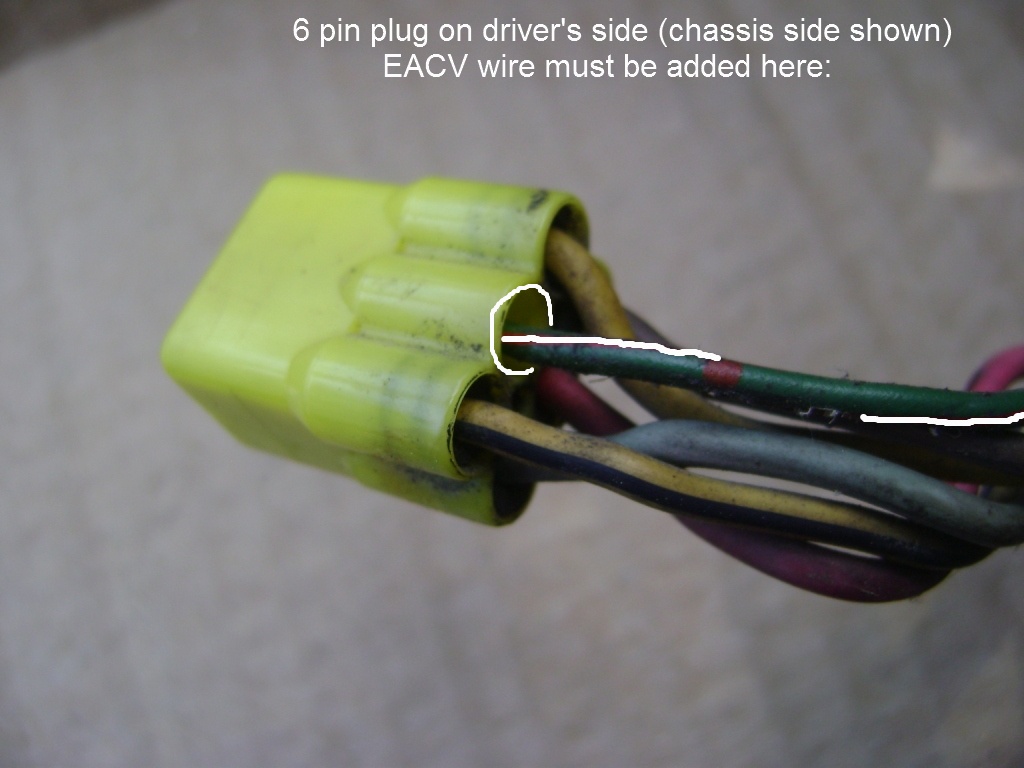
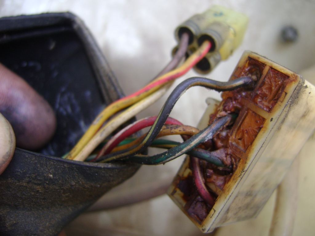
On the driver's side, the 6 pin chassis side connector is missing a wire for EACV actuation. You'll be getting rid of the Civic emissions box located behind the driver's side headlight leaving you with two unused connectors. Take the GRN/WHT wire from one of these connectors and plug it into the 6 pin plug as shown in the picture below. You will need to change the metal pin on this wire to be able to plug it in.
EMISSIONS CONTROL BOX WIRING
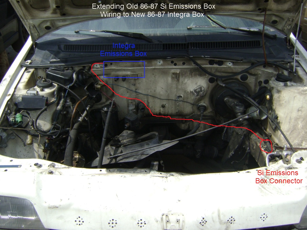
Since the Integra emissions control box (which replaces the Civic one) sits on the opposite side of the engine bay, you need to extend some of the wiring to reach. On the old emissions box connector you should find 3 wires: BLK/YEL, RED/WHT and YEL. Add enough wire to these to reach across to the other side of the bay (as shown below). Connect these to the Integra control box plug; BLK/YEL goes to BLK/YEL, RED/WHT to RED/WHT and YEL to WHT/YEL.
The Integra control box also houses the MAP sensor. It uses a different plug than the Civic so you need to swap over to the Integra connector. The new connections are as follows:
RED to REDYou can now plug in and mount the Integra control box.
Final Install:
This swap gets pretty tricky. Unlike a carb to FI swap or a Browntop swap, you will need to tear into the chassis harness and add/remove/more around a good amount of wires. This guide will get very confusing and hard to follow due to the amount of wiring changes needed, so I suggest reading it over a few times and making sense of it before attempting the actual swap on your car.
"EASY WAY" AND "HARD WAY"
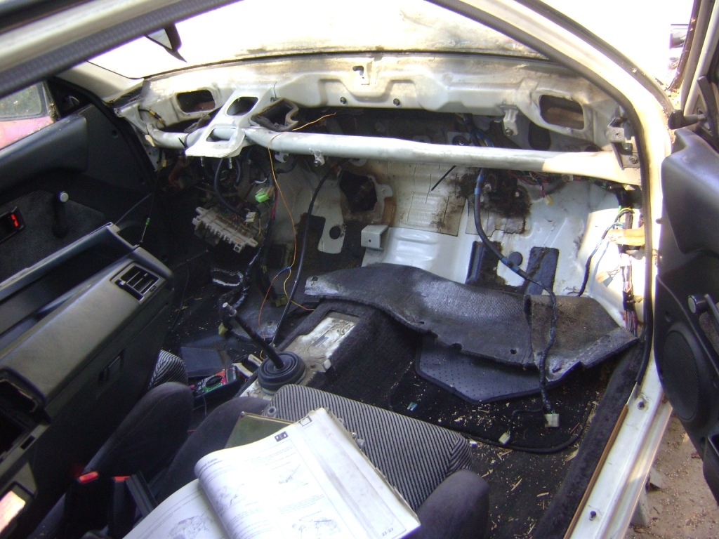
There are a couple of ways of peforming a Blacktop swap. First is the "hard way", which involves removing the dash and all underdash components to gain access to the underdash harness. The main objectives of this method are removing wiring that is no longer needed and running coil power/tach signal wires hidden under the dash instead of exposed across the engine bay. This method is really only suited for: A. anal types or show cars, B. people that love challenges or C. cars that need to look as OEM as possible for whatever reason. It is otherwise an awful lot of work for not a lot of gain.
The second is the "easy way", which is functionally similar to the "hard way". All vital electronic advance wiring is run through the passenger side (without having to remove the dash), and coil power/tach signal and emissions control box wiring is simply extended to reach across the engine bay. This is the route I recommend taking and the one most people will be content with.
A FEW THINGS TO NOTE
You will need to score an interior FI harness out of an 88-89 Integra, similar to what is needed on a carb to Browntop swap. If you are taking the "easy way", you can get away with only a smaller section as shown in the picture below:
On the swaps I've done, there are a few sensors/connections that I've left out. I have done testing with and without these and found that they have little to no effect on the way the car runs.
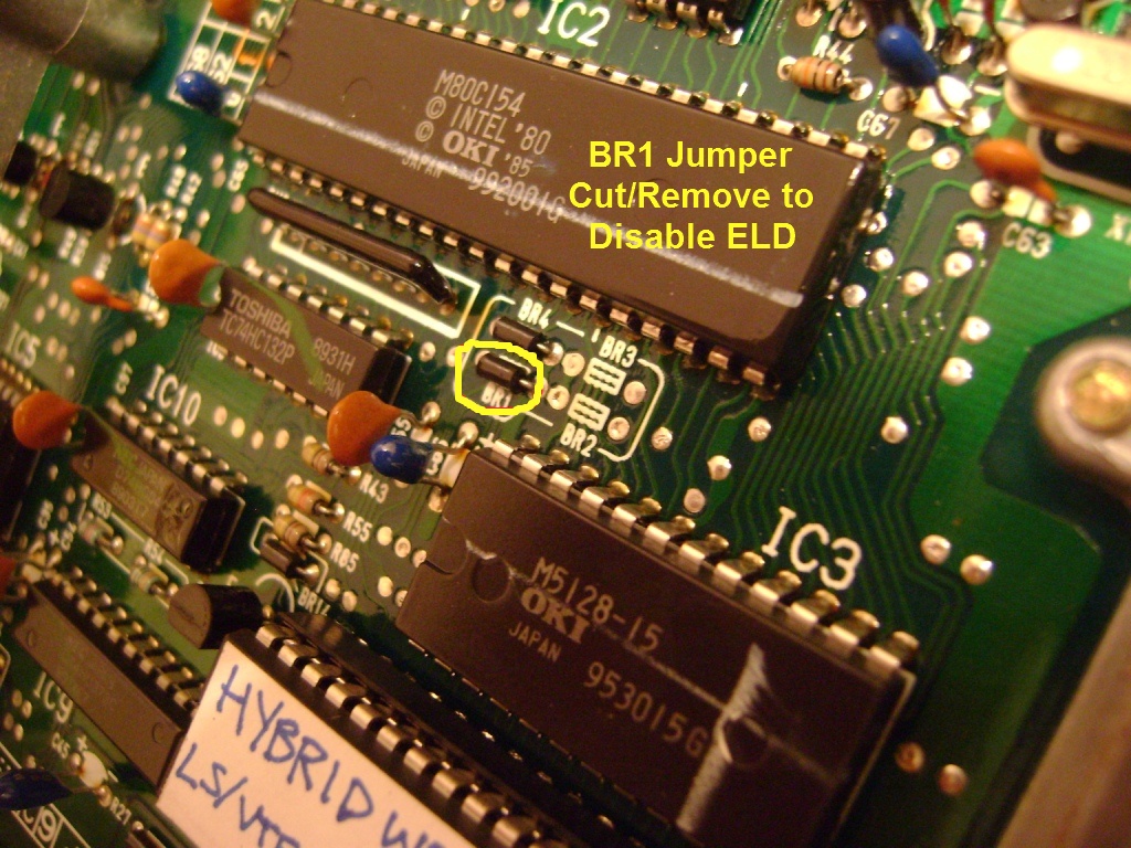
It's up to you which of these, if any, you want or need to use.
ELECTRONIC ADVANCE WIRING
Like the donor harness for a Browntop swap, most of the wiring will end up being junk. For a Blacktop swap, you will need even less wiring from the Integra donor harness, probably about a dozen wires total. Below is a list of the wires you will need to pull from it, complete and uncut from pin to pin:
The items marked with an asterisk (*) are not needed if taking the "easy way". The wires already exist on the driver's side of the engine bay, and can simply be extended to reach the new Integra emissions control cluster on the firewall.
Igniter and Crank Angle Sensor wires lead to a 6 pin add-on connector on the engine bay side. When removing these from the donor harness make sure not to remove or cut this plug off. Also, Cylinder Angle Sensor wires are wrapped in a bright-colored protective shielded covering. Don't attempt to remove it, use these wires as-is.
You will need to be able to de-pin the ECU plugs to remove the wires from the donor harness and again when you add them to the Civic's. Click below for a tutorial:
De-pinning TutorialOnce you have all the wires out of your donor harness, it's time to start unwrapping the Civic harness.
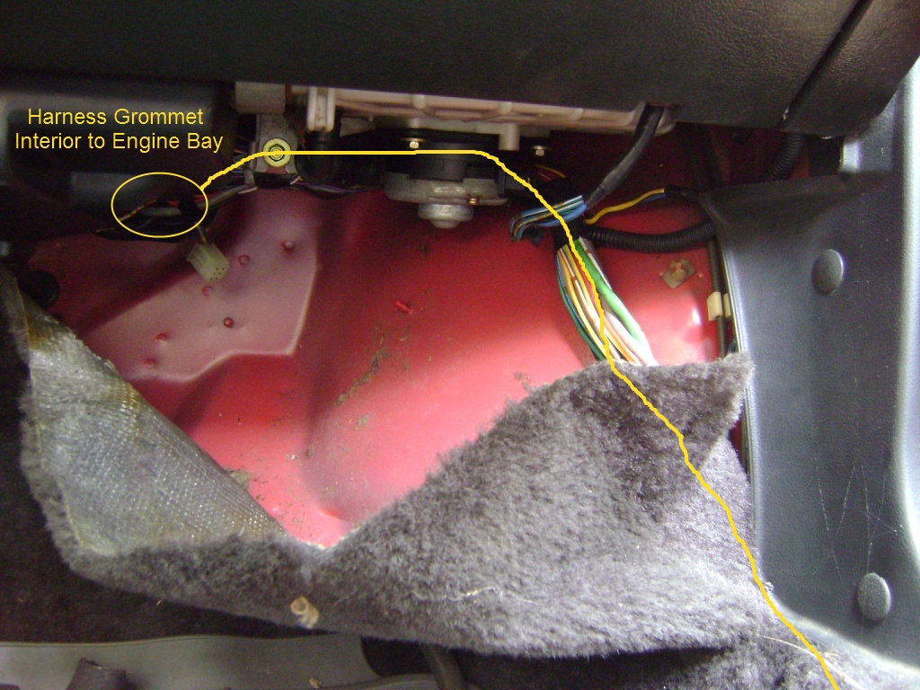
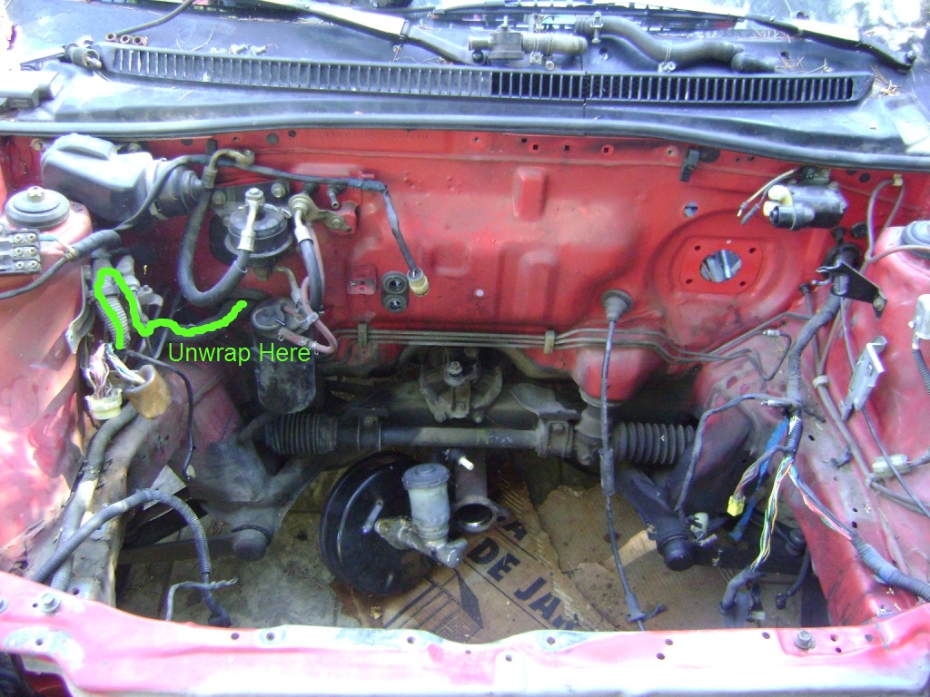
Start at the ECU plugs and work your way forward towards the engine bay, unwrapping old tape and removing the flexible wiring loom. Don't throw any loom away, you'll need it later. The first picture above shows the under dash portion of the harness which needs to be unwrapped, but you'll probably need to peel back or tear out the sound deadening mat to gain access first.
Once the inside portion is done, continue on the engine bay side as shown in the second picture above.
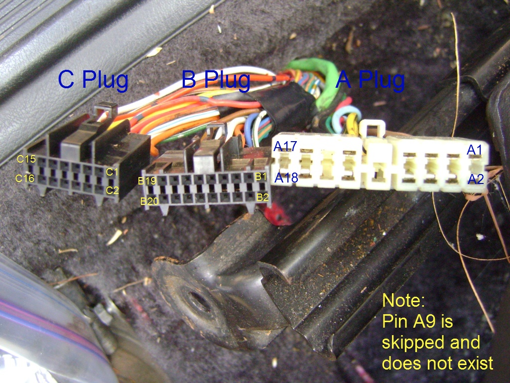
Now you'll need to start removing a couple of unused wires from the ECU plugs. Locate pins A8 (GRN/BLK), B4 (GRN/YEL), B17 (RED/WHT) B20 (WHT/YEL). If going the "hard way", de-pin and remove them from the connectors. You'll then need to follow these wires (under the dash) to the old Civic emissions control box and remove them completely. If going the "easy way", move pins A8 to A6 and B4 to B2. Pull the rest of the wires out of the way a little and tape up the ends.
Using the picture above for reference if necessary, start plugging your new wires into the ECU plugs. Most of them just plug into the same pins they came from on the Integra harness, as shown below:
Pins A17 and B1 require a bit of special attention. Remove pin A17 (WHT/GRN) and move it to pin B1. You won't be able to plug it in since the pin is physically different, but you should have a short piece of wire from the donor harness with the correct pin. Connect these two wires and solder them together.
Pin A17 should now be empty. Plug the BLK/YEL wire you took from the donor harness into this empty pin and run it into the engine bay.
The ORN and WHT Crank Angle Sensor wires that were added came from pins B10 and B12 on the donor harness. You will need to switch these with the ORN and WHT wires on pins C1 and C2. Basically, de-pin C1 and C2 and plug them into B10 and B12, which are empty. ORN goes to B10 and WHT to B12. Now add the new ORN and WHT wires to C1 and C2, with ORN going to C1 and WHT to C2. This now converts the wires you added from Crank Angle Sensor to Cylinder Position Sensor wires and will be referred to as such from now on. I know this step is confusing, but if you don't do this the car will not start once you are done.
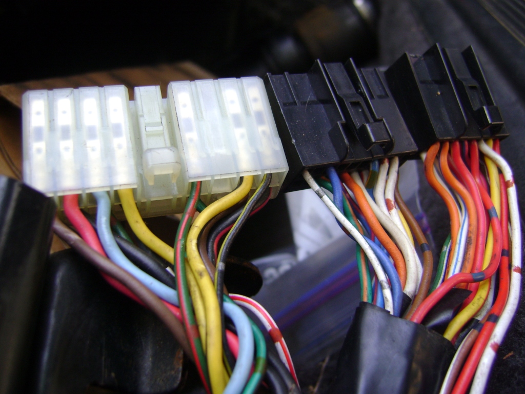
Once all your new wires are added, your ECU connectors and wiring should look like this:
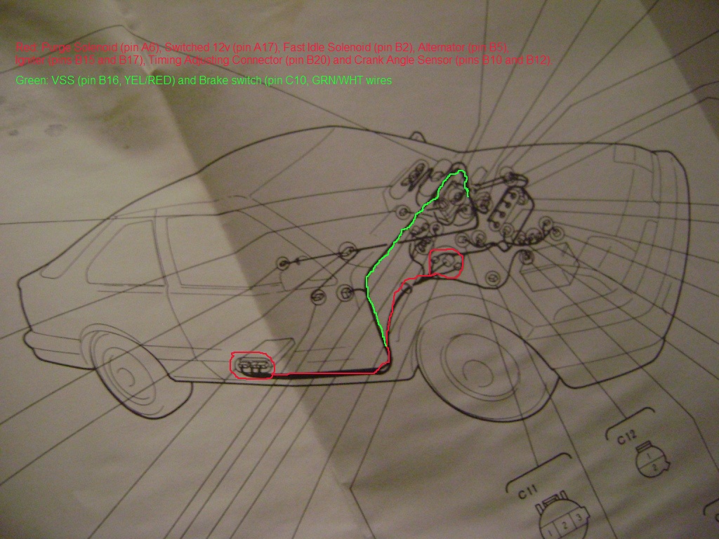
Now you need to run the VSS and Brake Switch wires across to the driver's side. The YEL/RED VSS wire just needs to be long enough to reach the gauge cluster area. Connect the VSS wire to one terminal of your VSS-capable speedo assembly (CRX HF, 88-91 Civic, etc.) and the other terminal to ground. For the Brake Switch wire, just tap directly into the GRN/WHT wire at the brake switch under the dash.
Run the wires you added through the firewall into the engine bay. At this point you should be left with wires for Alternator (BLU), two Cylinder Position Sensor wires (ORN and WHT, wrapped in shielded protector), Igniter (WHT), Timing Adjusting Connector (BRN) and Constant 12v wire (BLK/YEL). You should also have a Purge Solenoid (GRN) and Fast Idle Solenoid (BLU) wire if doing the swap the "hard way".
ENGINE BAY WIRING
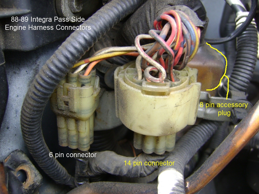
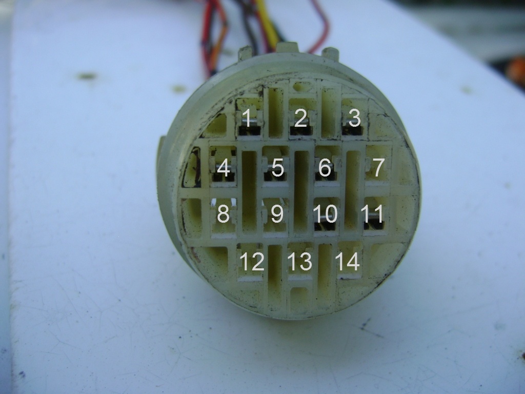
Plug the BLU Alternator wire into the Civic's 14 pin connector on the passenger side of the engine bay. Look for the lone empty pin (#7 on the connector shown above). The two Cylinder Position Sensor wires and single Igniter wire you fed into the engine bay should already be plugged into their own 6 pin add-on connector (as shown above). Timing Adjusting Connector wire should now be plugged into its connector and placed in a convenient, easy to reach place (as suggested in picture below). The other side of this connector should have a BRN/BLK wire that needs to be connected to the BRN/BLK wire on the #2 pin of the back of the 14 pin connector.
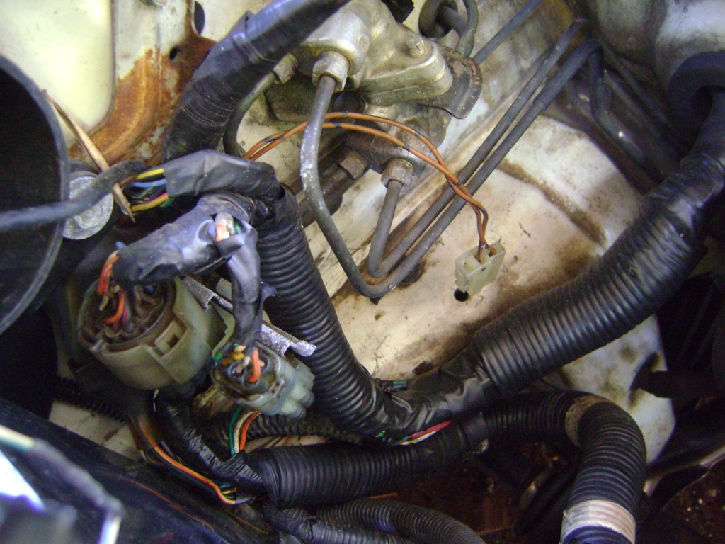
The 8 pin accessory plug will need to have some wires moved around as well. Move pin 1 (YEL/GRN) to pin 6, then move pin 5 (YEL/RED) to pin 7. Leave the leftover GRN/BLK and YEL reverse light wires hanging; you'll connect them later to the 6 pin Integra add-on connector.
Pins 1 and 5 are now empty. You'll need to extend the BLK/YEL and BLU wires from the old firewall-mounted ignition coil to this location. If taking the "hard way", pull these wires into the cabin and route them along the interior harness to the passenger side and into the engine bay again. You may need to add extensions for this wiring to reach. For the "easy way", simply lengthen them to reach across the engine bay and plug into the 8 pin connector. The BLK/YEL power wire will now live in pin 1 and the BLU tach signal in pin 5.
Finally, you'll need to connect a couple of wires to this connector. The Constant 12V BLK/YEL wire from ECU pin A17 should be connected to the BLK/YEL wire on pin 4 of the back of the accessory plug (constant 12V feed to the ECU). If taking the "hard way", you should tap a second power wire to the BLK/YEL wire at pin 4 and a ground wire to the BLK wire at pin 8. Run these to the firewall area; these will become power for the Fast Idle Solenoid and ground for the Purge Solenoid.
Your 6-pin add on connector now has two Cylinder Position Sensor and an Igniter wire connected to it. The GRN/BLK and YEL reverse light wires you removed from the 8 pin accessory plug will now be connected to this connector as well. Refer to the chart and picture below for pin locations. Note there are two white wires on this connector, be careful not to mix them up.
1. YEL REVERSE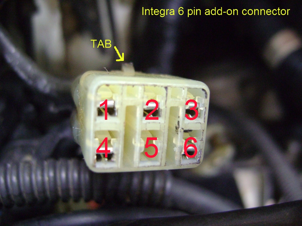
Now you'll need to run wiring for the Integra emissions solenoid cluster, which will be located on the firewall. If you took the "hard way", you should have a GRN Purge Solenoid wire, a BLU Fast Idle Solenoid wire, BLK/YEL power wire and a BLK ground wire. Hook these up to the connector on the Integra emissions cluster, matching the wires color for color.
The "easy way" will have you sourcing these same wires from the old Civic emission control box's connector on the driver's side. The GRN/BLK wire will be Purge Solenoid signal wire to the ECU, GRN/YEL will be Fast Idle Solenoid signal to the ECU and BLK/YEL is Fast Idle Solenoid power. For Purge Solenoid ground you have a couple of choices. Tap into the RED/WHT wire on the engine bay side, then on the ECU side take the same RED/WHT wire (from old pin B17, previously removed and taped up) and splice it into the BLK/RED ground wire at ECU pin A18. This converts RED/WHT into a ground wire at the old Civic emissions box connector. Alternatively, you can just connect the BLK wire from the Integra emissions cluster to ground directly on the firewall if you are not concerned about looks.
Lastly, change the plug on the old Civic MAP sensor to the new style Integra connector. RED goes to RED, WHT/RED to WHT and BRN/WHT to BRN/WHT.
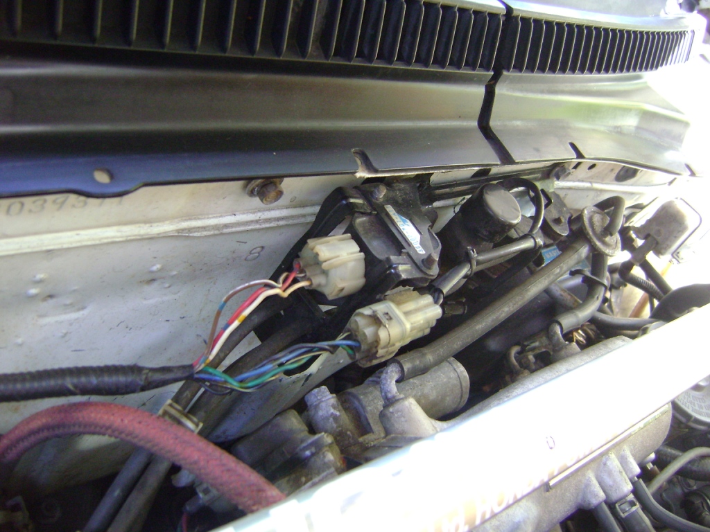
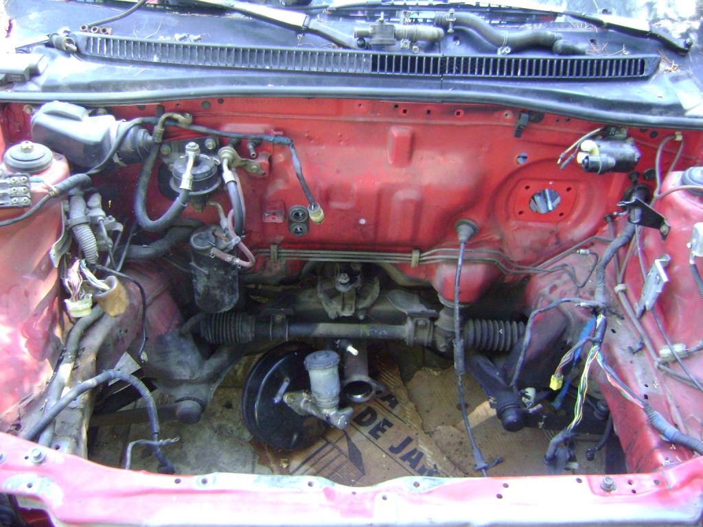
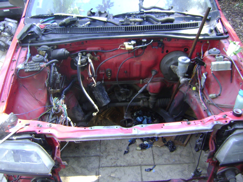
The last modification needed is to run EACV signal to the driver's side 6 pin connector. Take the GRN/WHT wire from the old Civic emissions control box connectors and run it to the empty pin on the 6 pin connector (see picture below).
Final Install:
